This post has a test piece for testing fitting:
viewtopic.php?f=6&t=22151&start=25#p133013
This video from tabandslot.com says they use 0.005 clearance on laser cut tables
I think I have read on here on people using as much as 0.020 on plasma, but I haven't really found a good post on it.
Need Help Improving Cut Quality
-
greg9504
- 1 Star Member

- Posts: 20
- Joined: Sat Apr 07, 2018 10:59 pm
-
robertspark
- 4.5 Star Elite Contributing Member

- Posts: 1815
- Joined: Mon Jun 12, 2017 6:43 pm
Re: Need Help Improving Cut Quality
The rounded corners are because you are not running any path rules imo
Plasma has a lag between the top and bottom of the material.... More so on thicker stuff.....
Simple thing is you need to slow down on the inside corners a bit it allow the plasma lag catch up
The lag lines are about 10-15 degrees from the vertical. (At optimum cutting speed.... Less if you run slower and more if you run faster than the optimum speed)
Hence adding a path rule to slow down just a bit (the size of the rounded corner) will improve the corners.....
Watch out for slowing down too much or you will overcut the top of the corner and end up with a dogbone corner (not the way that a true dog bone is done with a router but similar to the below image)
Lock the thc from diving too as the kerf widens automatically when you slow down and turn it off when you leave the inside corner slow down zone
-
adbuch
- 6 Star Elite Contributing Member

- Posts: 8629
- Joined: Thu Sep 21, 2017 5:22 pm
- Location: Tucson, Arizona
- Contact:
Re: Need Help Improving Cut Quality
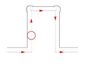
The 0.005" typical clearance mentioned in the video refers to the spacing between the mating parts. Laser cut parts with have virtually no taper, whereas plasma cut parts will have edge taper - although this can be minimized with the proper settings and consumables. The best approach may be to do a few test parts, see how they fit, and adjust your kerf setting accordingly. Also, as was previously mentioned, running slower on corners can help. For example - PlasmaCAM Design Edge software allows for the adjustments to corner speed and acceleration as shown below.greg9504 wrote: ↑Sat May 23, 2020 9:30 am This post has a test piece for testing fitting:
viewtopic.php?f=6&t=22151&start=25#p133013
This video from tabandslot.com says they use 0.005 clearance on laser cut tables
I think I have read on here on people using as much as 0.020 on plasma, but I haven't really found a good post on it.
David
- Cutting Motion.jpg (31.89 KiB) Viewed 796 times
-
whizbang
- 1.5 Star Member

- Posts: 33
- Joined: Tue Mar 24, 2020 1:45 pm
Re: Need Help Improving Cut Quality
Thanks for the feedback. I confirmed the height and have tried a few different and all the inside corners are rounded like that. My need for the square corners is for assembling parts intended to fit like puzzle pieces to be welded. I gave the development version of sheetcam a shot with the "overcut inside corner" feature and that has worked well on the first part.
I have some bugs in my file irrelevant to the corners, but none the less I am happy with the cut quality and now have the corner tolerance I needed.
I have some bugs in my file irrelevant to the corners, but none the less I am happy with the cut quality and now have the corner tolerance I needed.
- Attachments
-
-
-
plasmanewbie
- 5 Star Elite Contributing Member

- Posts: 2605
- Joined: Thu Jul 24, 2008 11:15 am
Re: Need Help Improving Cut Quality
Looking great! Glad you got it sorted out.
-
whizbang
- 1.5 Star Member
- Posts: 33
- Joined: Tue Mar 24, 2020 1:45 pm
Re: Need Help Improving Cut Quality
First of all, thank you everyone for the feedback.
I started to cut actual parts I would use and cut some mounting plates and decorative stuff from 12GA yesterday with a 45A nozzle at 45Amps. I used a new nozzle and struggled a bit with finding balance between reducing bevel and reducing dross. My edge looks better at about 60% of the recommended feed rate but I get a lot more dross.
My first question is - does anyone use a different cut height with their Hypertherm consumables when using sheilded versus unshielded? The Hypertherm manual calls out same cut height for both consumable set-ups but I have an IHS system so I would imagine that offset between the cup shield and the nozzle tip would throw off the actual cut height. Any thoughts? Should have I have a shorter cut height when using shielded consumables?
My next question is potentially tied to a THC issue, or maybe G Code, not sure. Yesterday I was cutting a decorative piece and I did the part in pieces since it was my first detailed part with lots of curves and small pieces. Part came out well for it's purpose but during the final cut of the outer perimeter the torch raised up pretty high, still cut but it was clear it was 2 to 3 times higher than it had been for all other cuts. There is excessive beveling in this area as well. In the image below the start point is marked by the green star, the yellow dots mark where the torch started the high cut. Outer cut was in the clock wise direction. I used sheetcam and this is only the 2nd part I have cut since I updated to the v1.5 sheetcam post process. I had to update the post processor for my Langmuir Crossfire Pro because I was having an issue where holes were randomly piercing but not fully cutting.
I made point to look at fire control when the torch went high thinking my THC was having issues but there was no errors during any cut on the part and THC looked to be running normally during the cut between the yellow lines. Any ideas what is going on?
Lastly - Anyone using sheetcam know of a way to program a return to XY zero and pause between parts or cut layers instead of having to post process each layer individually and run them as separate files?
Thanks in advance.
- Attachments
-
-
acourtjester

- 6 Star Elite Contributing Member
- Posts: 7784
- Joined: Sat Jun 02, 2012 6:04 pm
- Location: Pensacola, Fla
Re: Need Help Improving Cut Quality
Here is a code pause that I use between layers in the cut plan. And another code to return to X and Y zero that I just made for this post that should work find. Now the placement in the plan is what makes the difference. I use the pause when I am center punching drill holes to mark dimples on the metal at lowest amp setting. SheetCam will group them in a single plan by setting them as a "no offset layer" even with my planning all the parts together with both dimples and full part cut. When planning the last part with a dimple I add the pause code tool at that point. You could add the XY zero code tool then too, SheetCam separates the 2 types of cuts. To restart the cutting operation I hit cycle start, SheetCam then has the g-code cut all the remaining parts starting with the first real cut at full amps.
These videos show how it works
These videos show how it works
DIY 4X4 Plasma/Router Table
Hypertherm PM65 Machine Torch
Drag Knife and Scribe
Miller Mig welder
13" metal lathe
Small Mill
Everlast PowerTig 255 EXT
Hypertherm PM65 Machine Torch
Drag Knife and Scribe
Miller Mig welder
13" metal lathe
Small Mill
Everlast PowerTig 255 EXT