Test patterns

General software related questions should be posted here.
Post Reply
robertspark
4.5 Star Elite Contributing Member
Posts: 1816
Joined: Mon Jun 12, 2017 6:43 pm

Test patterns

Post by robertspark »

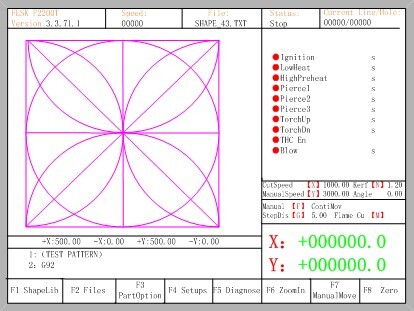
Has anyone run one of these test patterns?

I know hypertherm have one in their phoenix shape cutting software as do a few other manufacturers such as fangling (probably copied from somewhere else)

Image

I presume that they are run with just a Sharpie attached to the z axis....

Question.... Do they run as one loop (if so how)
Or do they draw a square, circle, arcs and crosses with the z axis raising and lowering

I have heard of the square, diamond and circle test, but that seems mainly for milling or routers.
https://www.google.com/url?sa=t&source= ... TxA_wrAP7N
User avatar
djreiswig
4.5 Star Elite Contributing Member
Posts: 1938
Joined: Thu Nov 19, 2015 10:02 pm
Location: SE Nebraska

Re: Test patterns

Post by djreiswig »

Just tracing with my finger, I don't think it's possible to run that drawing continuously without going over a line more than once. I'm not sure if that is acceptable or not.
2014 Bulltear (StarLab) 4x8
C&CNC EtherCut
Mach3, SheetCam, Draftsight
Hypertherm PM65
Oxy/Acetylene Flame Torch
Pneumatic Plate Marker, Ohmic, 10 inch Rotary Chuck (in progress)
robertspark
4.5 Star Elite Contributing Member
Posts: 1816
Joined: Mon Jun 12, 2017 6:43 pm

Re: Test patterns

Post by robertspark »

djreiswig wrote: Sat Jun 06, 2020 12:08 pm Just tracing with my finger, I don't think it's possible to run that drawing continuously without going over a line more than once. I'm not sure if that is acceptable or not.
Yup I've tried a few alternatives and I could not get it to work as 1 line (like the drawing a house with a single line trick)

Image

Curious to know if anyone has ever run one of those how it runs.

Anyone curious here are the hypertherm shapes from page 177 to 316, with the test image on the last page.
https://www.hypertherm.com/Download?fileId=HYP111796
ScottRa
2 Star Member
2 Star Member
Posts: 71
Joined: Wed May 13, 2020 4:23 pm

Re: Test patterns

Post by ScottRa »

Just a long winded method of cutting a square hole. ;)

The pieces could make a kids jigsaw puzzle.
robertspark
4.5 Star Elite Contributing Member
Posts: 1816
Joined: Mon Jun 12, 2017 6:43 pm

Re: Test patterns

Post by robertspark »

:HaHa

Yes, I was curious if it provided something more ... Maybe it would accentuate an issue on 1 stepper motor or axis in lieu of the others (kind of thought hypertherm probably came up with it for a purpose in drive / axis fault diagnosis in lieu of cutting a simple square, circle and diamond
User avatar
acourtjester
6 Star Elite Contributing Member
Posts: 7793
Joined: Sat Jun 02, 2012 6:04 pm
Location: Pensacola, Fla

Re: Test patterns

Post by acourtjester »

I'm not sure if it is to be one loop or is it that important. As with many test patterns to repeat the shape exactly, if a straight line is to short or long. Or the arcs do not intersect as they should would then show a problem. As Robert said I think it is to drawn to check the operations of a table.
DIY 4X4 Plasma/Router Table
Hypertherm PM65 Machine Torch
Drag Knife and Scribe
Miller Mig welder
13" metal lathe
Small Mill
Everlast PowerTig 255 EXT
ScottRa
2 Star Member
2 Star Member
Posts: 71
Joined: Wed May 13, 2020 4:23 pm

Re: Test patterns

Post by ScottRa »

I was trying to picture what it would look like if the x and y weren’t equal. Not sure if something would really stand out if they weren’t matched. Might be interesting to draw it up and then stretch it in one axis a bit. It does bring up a question for me as I’ve not yet done much in sheetcam and that was some years ago. Is it a toolset that would let you draw something like this, like using a scriber to draw an image?
robertspark
4.5 Star Elite Contributing Member
Posts: 1816
Joined: Mon Jun 12, 2017 6:43 pm

Re: Test patterns

Post by robertspark »

There is a plugin for sheetcam created by Vmax549 (Terry) a few years ago

https://forum.sheetcam.com/viewtopic.php?f=11&t=6683

Beefy / mancavedweller (Keith) did a YouTube on it
ScottRa
2 Star Member
2 Star Member
Posts: 71
Joined: Wed May 13, 2020 4:23 pm

Re: Test patterns

Post by ScottRa »

Well, here’s what it looks like stretched. The most noticeable seems to be non perpendicular intersections.

4EC802BA-FB7E-4E25-B7FF-B8BF434DB676.png
User avatar
acourtjester
6 Star Elite Contributing Member
Posts: 7793
Joined: Sat Jun 02, 2012 6:04 pm
Location: Pensacola, Fla

Re: Test patterns

Post by acourtjester »

maybe it me but the circle does not look round
DIY 4X4 Plasma/Router Table
Hypertherm PM65 Machine Torch
Drag Knife and Scribe
Miller Mig welder
13" metal lathe
Small Mill
Everlast PowerTig 255 EXT
ScottRa
2 Star Member
2 Star Member
Posts: 71
Joined: Wed May 13, 2020 4:23 pm

Re: Test patterns

Post by ScottRa »

I agree, I can tell it’s flattened as well. I could have stretched it less and the circle might have been harder to discern. The diagonals at the middle and where they cross the circle are really obvious, but I’d agree with your earlier post that it’s probably more of a mechanical test than something like calibrating squareness.
adbuch
6 Star Elite Contributing Member
Posts: 8646
Joined: Thu Sep 21, 2017 5:22 pm
Location: Tucson, Arizona
Contact:

Re: Test patterns

Post by adbuch »

Not round or square.
David
Not round or square.jpg
adbuch
6 Star Elite Contributing Member
Posts: 8646
Joined: Thu Sep 21, 2017 5:22 pm
Location: Tucson, Arizona
Contact:

Re: Test patterns

Post by adbuch »

Original not round or square either.
Original not square either.jpg
robertspark
4.5 Star Elite Contributing Member
Posts: 1816
Joined: Mon Jun 12, 2017 6:43 pm

Re: Test patterns

Post by robertspark »

Confused....what are you guys looking at?

If you look in the back of the he hypertherm manual I posted earlier it only has one setting which is size (5")... But you can change it to whatever you want.

I thought it may be a useful test to run with G1 rapid movement and your design feedrate or your intended feedrate on a piece of A4 / letter paper with a Sharpie to show acceleration roundness visually

I drew one in DXF and have handballed some gcode together as a test as it's on my list of things to try out.

If you have a loose motor coupling or non square gantry it will probably show up as a quick start of the day or run test as I have a breakaway torch holder I could quick change swap out for a Sharpie holder.

Piece of paper on a clipboard with some bulldog clips to hold the paper down chucked on the table may work

Saves wasting steel and plasma consumable pierces and eliminates / identifies any mechanical issues from torch (consumables) issues?
User avatar
acourtjester
6 Star Elite Contributing Member
Posts: 7793
Joined: Sat Jun 02, 2012 6:04 pm
Location: Pensacola, Fla

Re: Test patterns

Post by acourtjester »

It seems to be in agreement that this is a test for table tightness and alignment. There have been many posts about using something like this to show if there is a problem. We all want the part we draw is cut by the table when they are not you are wasting metal, time and get frustrated.
This video show one of the ink pen holder I have made for doing just that, this one fits into the torch holder. The other is attached on the side. I have another 3-D printed one cannot find images of it now.
Attachments
DSCN0970.jpg
DSCN0971.jpg
cnc pen checker (4).JPG
cnc pen checker (3).JPG
DIY 4X4 Plasma/Router Table
Hypertherm PM65 Machine Torch
Drag Knife and Scribe
Miller Mig welder
13" metal lathe
Small Mill
Everlast PowerTig 255 EXT
robertspark
4.5 Star Elite Contributing Member
Posts: 1816
Joined: Mon Jun 12, 2017 6:43 pm

Re: Test patterns

Post by robertspark »

Tom

Is that a general ball point pen?

Impressed! I didn't think they would work very well and be able to keep up with the machine (hence me looking at sharpies)
User avatar
acourtjester
6 Star Elite Contributing Member
Posts: 7793
Joined: Sat Jun 02, 2012 6:04 pm
Location: Pensacola, Fla

Re: Test patterns

Post by acourtjester »

Yes sir just a replacement cartridge for standard Ink Pen, just has a larger ink storage. The center one is a BIC the free type from motel, banks, here is a bowl full take one home type :HaHa Both aluminum squares are drill for the pen size the bottom is not all the way with a small hole to its bottom for the pen tip to stick through. Top has a spring inside with a bolt to apply pressure. not much needed, just enough to hold pressure on the paper when marking. Generic post processor non-plasma to move the pen run the Z down to the paper with slight pressure zero it out maybe 0.050" G-code set to mark at 0.01" to mark.
cut height.JPG
cut height.JPG (50.42 KiB) Viewed 1083 times
DIY 4X4 Plasma/Router Table
Hypertherm PM65 Machine Torch
Drag Knife and Scribe
Miller Mig welder
13" metal lathe
Small Mill
Everlast PowerTig 255 EXT
robertspark
4.5 Star Elite Contributing Member
Posts: 1816
Joined: Mon Jun 12, 2017 6:43 pm

Re: Test patterns

Post by robertspark »

here is a gcode snippet for shunting an axis back and forth over a distance and it will increment the feedrate every time it goes back and forth (the code is well commented and I'm sure you can tailor it to your testing needs) by changing the parameters at the start of the code.

note I work in mm (so the feedrates and distances may look a little high if you work in inches)..... just change the bits at the start of the code to your units and it will work for you.

It works fine in UCCNC

edit: fixed with Mach3 (added square brackets)

Linuxcnc can use vars too but I don't know if the below code will work correctly


I thought I'd post it simply because I'm just dabbling with variables and writing some test gcodes.

It may help you out to develop your own routines and use M98 with sub-programs for repetitive operations.

Code: Select all

#10 = 2000 (initial feedrate)
#1 = 100 (feedrate increase)
#2 = 100 (travel distance)
#4 = 10 (number of times to repeat)


#3 = [#2 * -1]
#10 = [#10 - #1]

G92 X0
G91 (incremental distance mode)

M98 P2000 L#4

G90 (absolute distance mode)
M30


O2000 (sub-program to repeat)
#10 = [#10 + #1]
G1 X#2 F#10
G1 X#3
M99

robertspark
4.5 Star Elite Contributing Member
Posts: 1816
Joined: Mon Jun 12, 2017 6:43 pm

Re: Test patterns

Post by robertspark »

here is a simple code snippet to test / set the correct pierce delay or dimple between two times you set over a time increment you set.

Say you don't have a book setting for pierce times.

With this code snippet you can test the pierce times from 0mSec (or 0 Sec) to 1000mSec (or 1 Sec) in 100mSec (0.1Sec) increments by changing #3, #4 and #5 to the numbers you desire.

you can also adjust the spacing on the dimples with #1 and #2

and you can set the pierce height / dimple height with #7

you can set #8 and #6 to 0 (zero) if you don't have a THC or you don't have a touchoff macro...... BUT if yhou don't have a toughoff macro you will need to add in something like G31 Z-100 F500 (in metric) where #6 is shown in the sub-programme O2000 , and also G92 Zxxxx where xxxx is the negative (-) switch offset on the next line below G31.


If you do have a book that lists the pierce times.... then this macro may help you to test or hone those times to your setup .... you could change the increments from 100mSec to 50mSec or whatever etc (with #3 = 50 (mSec) or 0.05 (Sec))

You can also hone in around say 300mSec by choosing a range from say 100mSec (#4=100) to 500mSec (#5 = 500) and it will allow you to fine tune your pierce times so the divot is not larger than it needs to be and the material is just pierced before movement begins

Code: Select all

(PIERCE / DIMPLE SETTING TEST)
(distances in mm as shown)
(time in mSec as shown)

#1 = 15 (x spacing between pierces mm)
#2 = 0 (y spacing between pierces mm)
#3 = 100 (pierce time increment mSec)
#4 = 0 (start pierce time delay mSec)
#5 = 1000 (end pierce time delay mSec)
#6 = 3100 (touchoff macro number)
#7 = 3.8 (pierce / dimple height mm)
#8 = 205 (THC ON macro number)


#10 = [#5 - #4]
#10 = [#10 / #3]
#10 = [#10 + 1]

#11 = #1
#12 = #2

G90 G64
G92 X0 Y0  (set temp offset X&Y)
M#8 (THC ON)

M98 P2000 L#10

G0 X0 Y0
G92.1

M30


O2000 (sub-program to repeat)
M#6 (touchoff)
G0 Z#7 (retract to pierce height)
M3 (fire torch)
G4 P#4
M5 (torch off)
G0 Z10 (Z safe retract)

#4 = [#4 + #3]

G0 X#11 Y#12 (move to next pierce point)
#11 = [#11 + #1]
#12 = [#12 + #2]
M99
Post Reply

Return to “General Discussion”