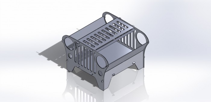
The "JEEP" Fire Pit
-
Dirtmotor
- 3 Star Elite Contributing Member

- Posts: 340
- Joined: Wed Aug 24, 2022 2:48 pm
Re: The "JEEP" Fire Pit
Thanks !
-
caretech
- 2 Star Elite Contributing Member

- Posts: 79
- Joined: Thu Jun 04, 2020 2:29 pm
- Location: SW Ontario
Re: The "JEEP" Fire Pit
What thickness do you fellows cut pits like this out of? 10ga? 3/16?
Shop-built 5x10 table powered by QtPlasmaC
Hypertherm PM 85 machine torch
Lincoln PowerMig 255C
Lincoln Square Wave Tig 255
Ermak SpeedBend Pro
Hypertherm PM 85 machine torch
Lincoln PowerMig 255C
Lincoln Square Wave Tig 255
Ermak SpeedBend Pro
-
adbuch
- 6 Star Elite Contributing Member

- Posts: 11446
- Joined: Thu Sep 21, 2017 5:22 pm
- Location: Tucson, Arizona
- Contact:
Re: The "JEEP" Fire Pit
I would expect 10 ga. or thicker. I think it all depends on if it will be more ornamental in nature or will see much actual use.
David
David
-
FeeFab
- 1/2 Star Member

- Posts: 1
- Joined: Thu Jan 25, 2024 3:26 pm
Re: The "JEEP" Fire Pit
This looks awesome! I can not wait to try and cut this to see how it comes out. Thanks for sharing!
-
akozman1979
- 1/2 Star Member
- Posts: 3
- Joined: Sun Mar 10, 2024 10:59 pm
Re: The "JEEP" Fire Pit
Question on this file, I was expecting to see all of the circles and arcs as just that, but when I got it for instance the headlight instead of being a circle is defined by 100s of small line segments. Did I do something wrong, or does my AutoCAD LT 2017 do something different with the file? I didn’t try it in Fusion 360 yet.
-
adbuch
- 6 Star Elite Contributing Member
- Posts: 11446
- Joined: Thu Sep 21, 2017 5:22 pm
- Location: Tucson, Arizona
- Contact:
Re: The "JEEP" Fire Pit
I don't think you did anything wrong. I see the same thing when I open it with Inkscape as well as Design Edge. I think this is just a result of the software the OP is using for his vector file creation. But it should still cut fine.akozman1979 wrote: Tue Mar 12, 2024 6:23 am Question on this file, I was expecting to see all of the circles and arcs as just that, but when I got it for instance the headlight instead of being a circle is defined by 100s of small line segments. Did I do something wrong, or does my AutoCAD LT 2017 do something different with the file? I didn’t try it in Fusion 360 yet.
David
You currently do not have access to download this file.
To gain download access for DXF, SVG & other files Click Here
-
adbuch
- 6 Star Elite Contributing Member
- Posts: 11446
- Joined: Thu Sep 21, 2017 5:22 pm
- Location: Tucson, Arizona
- Contact:
Re: The "JEEP" Fire Pit
As an example - TMCad allows for export of dxf files in four different formats.
Polyarc, Polyline, or Spline would generally be preferred over the Line format. Perhaps Tom Caudle will have some thoughts on this as well.
David
Polyarc, Polyline, or Spline would generally be preferred over the Line format. Perhaps Tom Caudle will have some thoughts on this as well.
David
You currently do not have access to download this file.
To gain download access for DXF, SVG & other files Click Here
-
akozman1979
- 1/2 Star Member
- Posts: 3
- Joined: Sun Mar 10, 2024 10:59 pm
Re: The "JEEP" Fire Pit
Thanks for the quick reply David. Yeah, I myself always try to stick with poly lines. We learned different ways.
-
adbuch
- 6 Star Elite Contributing Member
- Posts: 11446
- Joined: Thu Sep 21, 2017 5:22 pm
- Location: Tucson, Arizona
- Contact:
Re: The "JEEP" Fire Pit
akozman1979 wrote: Tue Mar 12, 2024 7:13 am Thanks for the quick reply David. Yeah, I myself always try to stick with poly lines. We learned different ways.
-
akozman1979
- 1/2 Star Member
- Posts: 3
- Joined: Sun Mar 10, 2024 10:59 pm
Re: The "JEEP" Fire Pit
Another thing with many line segments vs poly lines is in your CNC program each line segment is another line of g-code, so this file will get very large quickly. Where as if you have a circle the g-code is based on the center, diameter, etc. it ends up making a much smaller g-code file. My basic understanding is you want as few line segments or vertexes as necessary to define what you’re cutting so the g-code file isn’t unnecessarily large.
-
adbuch
- 6 Star Elite Contributing Member
- Posts: 11446
- Joined: Thu Sep 21, 2017 5:22 pm
- Location: Tucson, Arizona
- Contact:
Re: The "JEEP" Fire Pit
akozman1979 wrote: Tue Mar 12, 2024 7:18 am Another thing with many line segments vs poly lines is in your CNC program each line segment is another line of g-code, so this file will get very large quickly. Where as if you have a circle the g-code is based on the center, diameter, etc. it ends up making a much smaller g-code file. My basic understanding is you want as few line segments or vertexes as necessary to define what you’re cutting so the g-code file isn’t unnecessarily large.
You currently do not have access to download this file.
To gain download access for DXF, SVG & other files Click Here
-
adbuch
- 6 Star Elite Contributing Member
- Posts: 11446
- Joined: Thu Sep 21, 2017 5:22 pm
- Location: Tucson, Arizona
- Contact:
Re: The "JEEP" Fire Pit
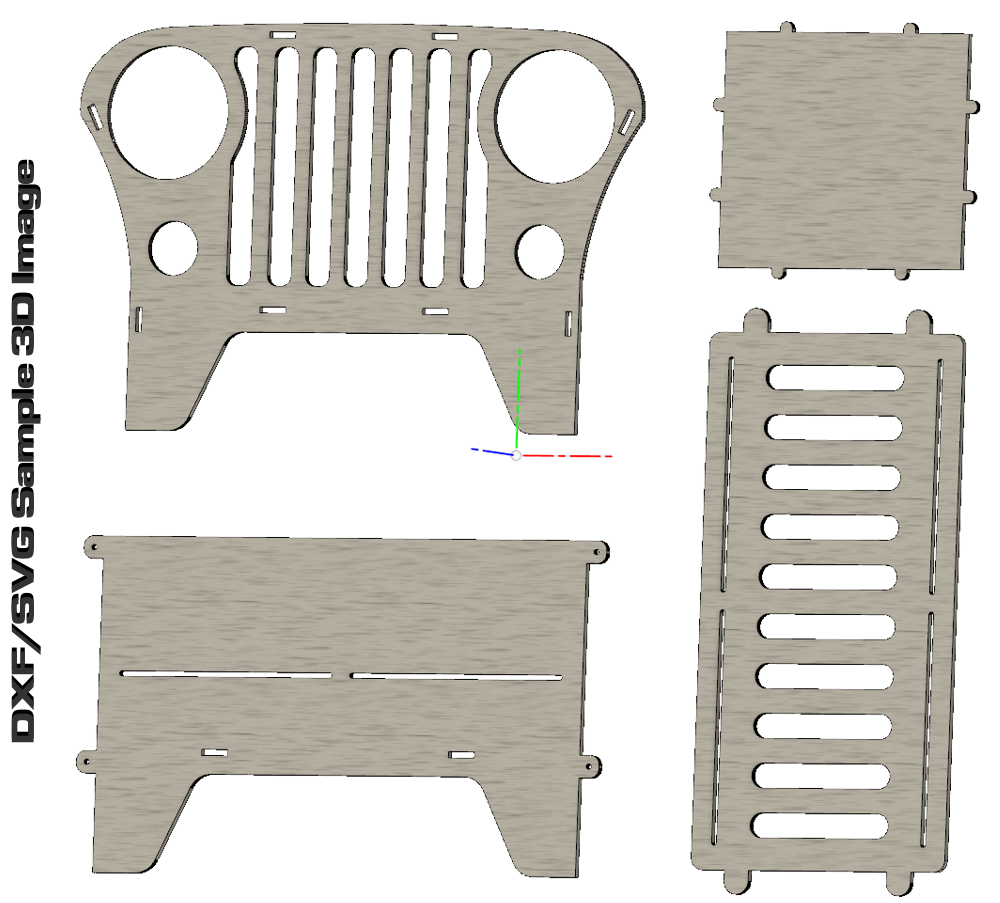
This is a great looking fire pit!! There was just someone at the one of the Plasmacam Facebook groups asking for a collapsible Jeep fire pit. I referred them to this page and let them know that if the become a contributing member they can download this one plus many others as well.Red Star wrote: Thu Jan 21, 2016 12:37 pm Hi everyone. I'm new to the page and saying hello. Amazing forum and I love all the shares. I was reading through the Jeep fire pit and saw some people were having trouble with tabs so I modeled it up in Solidworks and found some problems. I fixed them up for you all and would like to share them with you. Thanks for sharing everyone.
Jeep Pit Elevated - Grill.DXFJeep Pit Elevated - Side.DXFJeep Pit Elevated - End.DXFJeep Pit Elevated - Bottom.DXFJeep_Pit_All.dxf
David
-
SpeedRacer
- 1/2 Star Member
- Posts: 1
- Joined: Wed May 13, 2020 3:33 pm
Re: The "JEEP" Fire Pit
Curious what was the problem with the tabs? not enough clearance?
-
adbuch
- 6 Star Elite Contributing Member
- Posts: 11446
- Joined: Thu Sep 21, 2017 5:22 pm
- Location: Tucson, Arizona
- Contact:
Re: The "JEEP" Fire Pit
Red Star (the OP) has not been active on this forum since 2018, so I doubt he will respond to you. As far as I know, he never explained what the problems were with the original file. He did say in a follow-up post:SpeedRacer wrote: Wed Oct 23, 2024 8:34 am Curious what was the problem with the tabs? not enough clearance?
He did say that he had modeled it up in Fusion 360 for a fit check. If you know how to use Fusion 360, this would not be too hard to do. Each of the pieces can be imported (inserted) to Fusion 360 as dxf and extruded to the 3/16" thickness. Then simply assemble the pieces to see how they fit.Red Star wrote: Sat Jan 23, 2016 11:39 am Thank you for the replies. I kept the same thickness as the original and made the slots for 3/16" plate.
David
You currently do not have access to download this file.
To gain download access for DXF, SVG & other files Click Here